home | tumblrblog | musics | electronics | ask | about | more
So at the end of 2012, I decided to rewire my MCI B-35 Guitorgan for MIDI (and possibly OSC) functionality, since the internal synthesizer was dying a slow and noisy death.

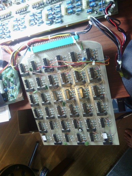
Before I get too far into things, you may be wondering what a guitorgan actually is. The Wikipedia article on it has a surprising amount of info about its history and operation, considering there were relatively few made and were expensive and somewhat rare. Basically, it’s a guitar with an organ inside of it. It has two outputs: one for the guitar’s normal signal, whose circuit ran independent of the organ’s circuitry (thankfully); and the other for the synthesized organ sounds. The organ is controlled by the strings coming in contact with the frets; the frets are divided into 6 parts, allow for individual contact switches for nearly all the notes on the guitar’s neck. For those who are curious, you can check out (most of) the schematic and layout for the organ here (sorry link down).
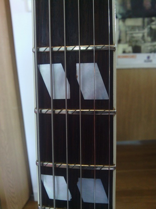
Since the organ was synthesized within the body of the guitar, it was an extremely (and almost impractically) heavy device. While vintage synthesizers are definitely cool, the sounds from it were remarkably plain and limited in my opinion. There were a total of three tones (“flute”, “accordion”, and “vibraphone”) along with other effects and the drawbars (which allowed for the sort of tone shaping you could get with a simple drawbar organ). Only the “flute” tone utilized the drawbars, and was the only one useful to me, mostly because I could “filter” out the noise by only having the lower tone bars turned up (which didn’t actually filter anything, but it had less oscillators active which meant less noise). All in all, I wasn’t very happy with the organ part of my guitorgan. And with the extra bulk from all that circuitry, playing the guitar part wasn’t exactly fun either, even though it was a decent Gibson knockoff (I believe it was a Japanese Aria, but I haven’t found definitive proof of that yet).

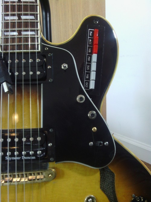
I had just finished taking a class on human/computer interfacing and design when I started the project. We mostly used the Arduino platform, which is basically an open-source hardware prototyping platform which is driven by a microcontroller that runs on easy-to-program C-like code. I decided to use it for this project since using the Arduino board would save me a lot of time trying to design a circuit that can convert the control signals to MIDI (or whatever). All I had to do was connect the existing sensors up to the Arduino board in the right way, write some code that would send the corresponding signals to a computer, and use any synthesis software I wanted that would recognize these signals.
The Hardware
Before I could dig into the details of the code, I had to understand exactly how the guitorgan worked in the first place. Luckily, I had most of the schematics handy, which revealed that nearly all the switches and potentiometers on the body were just that: simple switching and potentiometer circuits. This meant that I could simply remove the circuitry that these switches and pots were connected to and rewire them to be either digital switches that the Arduino could read, or variable analog voltage attenuators for the pots, which could feed into the analog inputs on the Arduino board. There were a couple of oddballs: the master tuning knob underneath the pickguard was actually a variable inductor, which would require a slightly more complicated circuit for the Arduino to understand. My particular model of guitorgan also had a relatively new feature: string actuators. It was basically a guitar pickup that could control the envelope of the organ sounds when enabled, thus only triggering the organ sounds when the corresponding string was vibrating. Unfortunately I didn’t have the schematic for that portion of the circuit, and given the scope of my project already, I decided to carefully remove it and save it for another time.
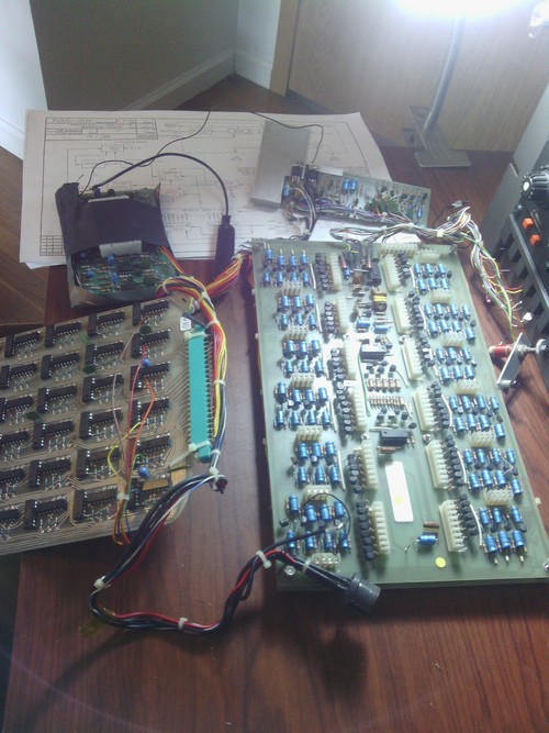
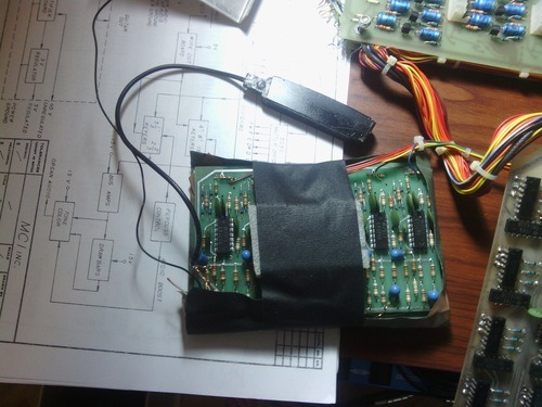
The “keying” system (the circuitry that made the contact switches on the guitar’s neck control organ) was pretty straightforward. Its operation is basically that of a bunch of SPST switches with a pull-up resistor (presumably built into the TTL logic chips each fret portion was wired to) with the strings being tied to ground. So, when the string is not pressed against a fret, a high voltage is read at the fret, and when the string is pressed down, a low voltage is read. Yay digital electronics!
The Circuitry
So once I had the sensors and knobs and switches figured out, I needed to plan out exactly how I was going to get all those digital signals (and some analog ones too) to be read by the Arduino in a manner fast enough for musical response. The total number of inputs was pretty staggering: 17 frets per string times 6 strings, plus 12 additional switches/buttons (and 5 analog pots on top of that); that requires 114 digital inputs and 5 analog ones!
Nowadays, I’d probably default to using shift registers, which are ideal for turning parallel digital signals into serial ones, which is essentially what we have here. Unfortunately at the time, I wasn’t really sure how shift registers worked, so I looked elsewhere.
I found that another common solution is to use a keyboard matrix, which basically reduces the number of inputs to a factor of the total (so an 11×11 matrix could be used here, for example), but that has two major issues: First, it would require more inputs than are available (the Arduino Uno only has 13 digital inputs, at least 1 of which is required for serial communication, with 2 needed for programming the board). And second, because of the way the contact switches work, it would be impossible for the keyboard matrix to be polyphonic because it requires a “scanning” system that allows voltages to go through each leg of the matrix independently, which is not possible with the common ground of the strings.
I decided at the time to go with a multiplexing system to get all the signals into the Arduino. A multiplexer has multiple parallel inputs that may be digital or analog signals and a single output which echoes a selected input. The output that is echoed can be controlled by the Arduino board by sending a parallel signal that is basically a binary number telling the multiplexer which input to echo. So, the Arduino continuously counts through the number of inputs on the multiplexer, and reads the single output on each count, thus reading all of the multiplexer’s inputs while only using a single input on the microcontroller. It can do this so quickly that it reads the signals present at the multiplexer’s inputs practically in real time (its speed is determined by the Arduino’s loop speed; in other words, how fast the Arduino can count, which is pretty dang fast). The most practical thru-hole multiplexer I could find was a 16-input, single output multiplexer that was a little large (24-pin, wide body), but I would only need 8 of them to take care of the job (though I would end up using 9 simply for spatial reasons).

The next step was removing the internal circuitry of the guitorgan, which was actually a lot of fun. I was initially very concerned about the copper magnet wires that was used to connect each fret to an individual leg of a logic chip, but the wires were very carefully wrapped in a logical way that allowed you to see how the strings were grouped together. I initially started to label each wire and its corresponding note, but I soon figured out the system and didn’t need to waste my time with all the labels. The wires were also surface mounted to the logic board, so removal with a soldering iron was a snap. Before long, all that remained in the guitorgan was the guitar circuitry, the bundle of copper wire, and the various switches and buttons. It was finally a playable weight!
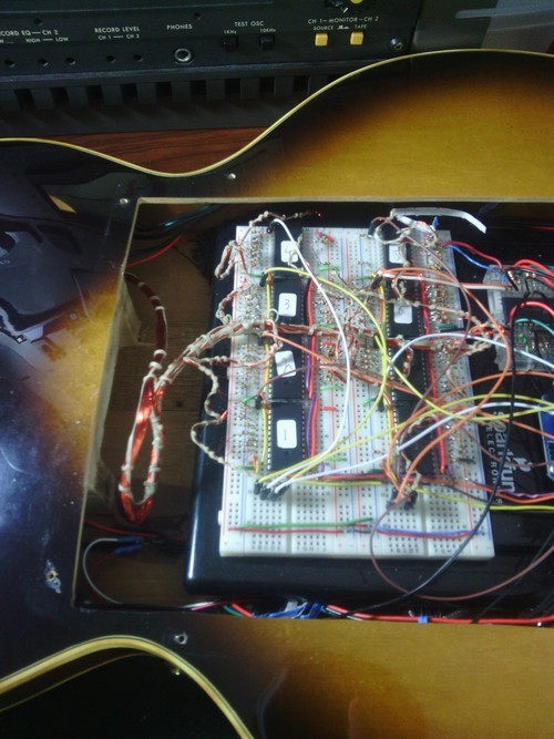
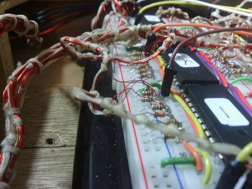
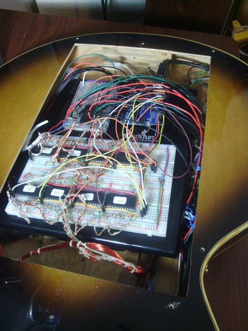
I didn’t want to invest in a custom PCB for the project, so I decided to breadboard everything. Needless to say, the work was tedious. Copper magnet wire is too fine to be inserted into a breadboard, and each connection needed a pull-up resistor in order to guarantee consistent functionality. Luckily, I was able to solve both problems by soldering each copper wire to a leg of a resistor and used that to insert into the breadboard, but this was still a tedious process. Eventually it all came together, and using some leftover pieces of plastic from other projects I was able to mount everything snugly inside the guitar’s body. The only goofy thing I still need to figure out is how to get the USB connection to be where the guitorgan output used to be…for now it is just a dangling USB cable, connected internally in the guitorgan.
The Code
As far as the code goes, it is a little more complicated than just loading a MIDI library to the Arduino and getting it to show up as a MIDI device on the computer. Rather, I programmed the Arduino to send very simple serial messages over USB any time a sensor value changes, which is much faster than trying to send relatively bulky MIDI messages. For now, I’m using Pure Data to receive the serial messages and convert them to MIDI messages, which I can send to pretty much any synth app I want. Obviously I could do much more research into this topic, but it works great for my purposes. And it is much more flexible than just committing the guitorgan to work with just MIDI, because I could easily write a PD patch that converts the serial messages into OSC messages, for example.
Being a fan of Arduino and PD and open source stuff in general, I’ve been working on an open source PCB design (in Fritzing, also open source software) that utilizes an Arduino Nano, shift registers, and a couple of multiplexers to do what I did with the breadboard. I haven’t worked on the code yet, mostly because I’d like to have the hardware to work with while I write it, and I haven’t the resources at the moment to get a prototype board shipped. But! If you are interested in helping me out you can always contact me (just include you email in the message). I’d totally be willing to fit anyone’s old broken guitorgan with this system if they’d be willing to cover the costs and small labor fee (very small, I promise). Or, there should be enough info here to do it yourself! If you want more information or the code I used, feel free to ask. If I get enough inquiries I might just make a tutorial 🙂 .
As for the guitar itself, you can find my modified wiring at the bottom of this page. It’s a pretty standard Gibson-style layout with two humbuckers, but I’ve converted the poorly emulated Vari-tone switch into a pickup wiring selector.
Here’s a clip of it in action:
https://youtube.com/watch?v=VBtC9OVmhHc